Oh yes.. here I am thinking about the most beautiful and attractive suit Iron man. Is it only a fictional suit made for just entertainment purpose or we can actually make?.. So the major problem of the suit is power supply.. Arc reactor is hard to make but do we have any substitute fuel? Let me think... lets sort out few fuels.. I would start with fossil fuels.. Fossil fuels have combustion percentage of about 60-90% but they are costly.. and even if we make it it will produce lot of air pollution. Next.. lets take few green energy sources.. can we use air, water or any other thing? Why not use water as a source.. Let me simplify this.. We have already seen electrolysis in our school level.. we shall use electrolysis to separate the hydrogen and oxygen from the water. Next we know hydrogen is combustible and oxygen supports combustion so why not use this now and make fully controlled compact reaction chamber to follow this reactions.. I actually don't know about the thrust we shall get after this but this technology can be improved and certainly it will b very easy to make a suit.
Monday, 23 September 2013
Saturday, 21 September 2013
As Life Passes...
As Life Passes i was becoming stronger day by day.. I came to know about few types of people on earth. And the major fellas where hypocrites. Dealing with hypocrites is a tough job, as you know that they wear a good quality of mask on there faces. But as life passes and after few shocking experiences I came to know that i was being used by others. My knowledge, my skills, my information, everything I had was being copied and I was not aware of it. No sooner i reached at my Intermediate/+2 where I felt a lot of responsibilities are out their for me in life. I was preparing for India's one of the most toughest entrance exam and that was IIT-JEE. I had a correspondence course from Mumbai's best coaching center. Though that was a critical time for me to make my dream come true but unfortunately I couldn't. Lack of concepts, knowledge, understanding things lead me to doors of failure. Even though i used to work hard but still there was something missing in my preparations. I was not at all learning anything though i knew everything. Let me clear this out for you guys.. You might see people in your life who knows everything but don't understand anything. Knowing something is good its like an information but understanding those things is the best job you are doing continued
Thursday, 12 September 2013
RAILWAY AIR BRAKE
An air brake is a conveyance braking system actuated by compressed air. The Westinghouse system uses air pressure to charge air reservoirs
(tanks) on each car. Full air pressure signals each car to release the
brakes. A reduction or loss of air pressure signals each car to apply
its brakes, using the compressed air in its reservoirs.
In order to design a system without the shortcomings of the straight air system, Westinghouse invented a system wherein each piece of railroad rolling stock was equipped with an air reservoir and a triple valve, also known as a control valve.
The triple valve is described as being so named as it performs three functions: Charging air into an air tank ready to be used, applying the brakes, and releasing them. In so doing, it supports certain other actions (i.e. it 'holds' or maintains the application and it permits the exhaust of brake cylinder pressure and the recharging of the reservoir during the release). In his patent application, Westinghouse refers to his 'triple-valve device' because of the three component valvular parts comprising it: the diaphragm-operated poppet valve feeding reservoir air to the brake cylinder, the reservoir charging valve, and the brake cylinder release valve. When he soon improved the device by removing the poppet valve action, these three components became the piston valve, the slide valve, and the graduating valve.
Under the Westinghouse system, therefore, brakes are applied by reducing train line pressure and released by increasing train line pressure. The Westinghouse system is thus fail safe—any failure in the train line, including a separation ("break-in-two") of the train, will cause a loss of train line pressure, causing the brakes to be applied and bringing the train to a stop, thus preventing a runaway train.
In addition, an emergency application brings in an additional component of each car's air brake system: the emergency portion. The triple valve is divided into two portions: the service portion, which contains the mechanism used during brake applications made during service reductions, and the emergency portion, which senses the immediate, rapid release of train line pressure. In addition, each car's air brake reservoir is divided into two portions—the service portion and the emergency portion—and is known as the "dual-compartment reservoir”. Normal service applications transfer air pressure from the service portion to the brake cylinder, while emergency applications cause the triple valve to direct all air in both the service portion and the emergency portion of the dual-compartment reservoir to the brake cylinder, resulting in a 20–30% stronger application.
The emergency portion of each triple valve is activated by the extremely rapid rate of reduction of train line pressure. Due to the length of trains and the small diameter of the train line, the rate of reduction is high near the front of the train (in the case of an engine operator-initiated emergency application) or near the break in the train line (in the case of the train line coming apart). Farther away from the source of the emergency application, the rate of reduction can be reduced to the point where triple valves will not detect the application as an emergency reduction. To prevent this, each triple valve's emergency portion contains an auxiliary vent port, which, when activated by an emergency application, also locally vents the train line's pressure directly to atmosphere. This serves to propagate the emergency application rapidly along the entire length of the train.
Passenger trains have had for a long time a 3-wire version of the electro-pneumatic brake, which gives seven levels of braking force. In most cases the system is not fail-safe, with the wires being energized in sequence to apply the brakes, but the conventional automatic air brake is also provided to act as a fail safe, and in most cases can be used independently in the event of a failure of the EP brakes.
. On the conventional side, the control valve set a reference pressure in a volume, which set brake cylinder pressure via a relay valve. On the electric side, pressure from a second straight-air trainline controlled the relay valve via a two-way check valve. This "straight air" trainline was charged (from reservoirs on each car) and released by magnet valves on each car, controlled electrically by a 3 wire trainline, in turn controlled by an "electro-pneumatic master controller" in the controlling locomotive. This controller compared the pressure in the straight air trainline with that supplied by a self lapping portion of the engineers valve, signaling all of the "apply" or "release" magnets valves in the train to open simultaneously, changing the pressure in the "straight air" trainline much more rapidly and evenly than possible by simply supplying air directly from the locomotive. The relay valve was equipped with four diaphragms, magnet valves, electric control equipment, and an axle-mounted speed sensor, so that at speeds over 60 mph (97 km/h) full braking force was applied, and reduced in steps at 60 mph (97 km/h) 40 and 20 mph (64 and 32 km/h), bringing the train to a gentle stop. Each axle was also equipped with anti-lock brake equipment. The combination minimized braking distances, allowing more full-speed running between stops. The "straight air" (electro-pneumatic trainline), anti-lock, and speed graduating portions of the system were not dependent on each other in any way, and any or all of these options could be supplied separately.
Later systems replace the automatic air brake with an electrical wire (in the UK, at least, known as a "round the train wire") that has to be kept energized to keep the brakes off.
Limitations
The Westinghouse air brake system is very trustworthy, but not infallible. Recall that the car reservoirs recharge only when the brake pipe pressure is higher than the reservoir pressure, and that the car reservoir pressure will rise only to the point of equilibrium. Fully recharging the reservoirs on a long trian can require considerable time (8 to 10 minutes in some cases), during which the brake pipe pressure will be lower than locomotive reservoir pressure.
If the brakes must be applied before recharging has been completed, a larger brake pipe reduction will be required in order to achieve the desired amount of braking effort, as the system is starting out at a lower point of equilibrium (lower overall pressure). If many brake pipe reductions are made in short succession ("fanning the brake" in railroad slang), a point may be reached where car reservoir pressure will be severely depleted, resulting in substantially reduced brake cylinder piston force, causing the brakes to fail. On a descending grade, the unfortunate result will be a runaway.
In the event of a loss of braking due to reservoir depletion, the engine driver may be able to regain control with an emergency brake application, as the emergency portion of each car's dual-compartment reservoir should be fully charged—it is not affected by normal service reductions. The triple valves detect an emergency reduction based on the rate of brake pipe pressure reduction. Therefore, as long as a sufficient volume of air can be rapidly vented from the brake pipe, each car's triple valve will cause an emergency brake application. However, if the brake pipe pressure is too low due to an excessive number of brake applications, an emergency application will not produce a large enough volume of air flow to trip the triple valves, leaving the engine driver with no means to stop the train.
Since the main reservoir pipe is kept constantly pressurized by the locomotive, the car reservoirs can be charged independently of the brake pipe, this being accomplished via check valve to prevent backfeeding into the pipe. This arrangement helps to reduce the above described pressure loss problems, and also reduces the time required for the brakes to release, since the brake pipe only has to recharge itself.
Main reservoir pipe pressure can also be used to supply air for auxiliary systems such as pneumatic door operators or air suspension. Nearly all passenger trains (all in the UK and USA), and many freights, now have the two-pipe system.
Straight air brake
In the air brake's simplest form, called the straight air system, compressed air pushes on a piston in a cylinder. The piston is connected through mechanical linkage to brake shoes that can rub on the train wheels, using the resulting friction to slow the train. The mechanical linkage can become quite elaborate, as it evenly distributes force from one pressurized air cylinder to 8 or 12 wheels.
The pressurized air comes from an air compressor in the locomotive and is sent from car to car by a train line made up of pipes beneath each car and hoses between cars. The principal problem with the straight air braking system is that any separation between hoses and pipes causes loss of air pressure and hence the loss of the force applying the brakes. This could easily cause a runaway train. Straight air brakes are still used on locomotives, although as a dual circuit system, usually with each truck having its own circuit.
Westinghouse air brakeIn order to design a system without the shortcomings of the straight air system, Westinghouse invented a system wherein each piece of railroad rolling stock was equipped with an air reservoir and a triple valve, also known as a control valve.
The triple valve is described as being so named as it performs three functions: Charging air into an air tank ready to be used, applying the brakes, and releasing them. In so doing, it supports certain other actions (i.e. it 'holds' or maintains the application and it permits the exhaust of brake cylinder pressure and the recharging of the reservoir during the release). In his patent application, Westinghouse refers to his 'triple-valve device' because of the three component valvular parts comprising it: the diaphragm-operated poppet valve feeding reservoir air to the brake cylinder, the reservoir charging valve, and the brake cylinder release valve. When he soon improved the device by removing the poppet valve action, these three components became the piston valve, the slide valve, and the graduating valve.
- If the pressure in the train line is lower than that of the reservoir, the brake cylinder exhaust portal is closed and air from the car's reservoir is fed into the brake cylinder to apply the brakes. This action continues until equilibrium between the brake pipe pressure and reservoir pressure is achieved. At that point, the airflow from the reservoir to the brake cylinder is lapped off and the cylinder is maintained at a constant pressure.
- If the pressure in the train line is higher than that of the reservoir, the triple valve connects the train line to the reservoir feed, causing the air pressure in the reservoir to increase. The triple valve also causes the brake cylinder to be exhausted to the atmosphere, releasing the brakes.
- As the pressure in the train line and that of the reservoir equalize, the triple valve closes, causing the air pressure in the reservoir and brake cylinder to be maintained at the current level.
Under the Westinghouse system, therefore, brakes are applied by reducing train line pressure and released by increasing train line pressure. The Westinghouse system is thus fail safe—any failure in the train line, including a separation ("break-in-two") of the train, will cause a loss of train line pressure, causing the brakes to be applied and bringing the train to a stop, thus preventing a runaway train.
Modern systems
Modern air brake systems serve two functions:- The service brake system, which applies and releases the brakes during normal operations, and
- The emergency brake system, which applies the brakes rapidly in the event of a brake pipe failure or an emergency application by the engine operator (generally referred to as the automatic brake).
In addition, an emergency application brings in an additional component of each car's air brake system: the emergency portion. The triple valve is divided into two portions: the service portion, which contains the mechanism used during brake applications made during service reductions, and the emergency portion, which senses the immediate, rapid release of train line pressure. In addition, each car's air brake reservoir is divided into two portions—the service portion and the emergency portion—and is known as the "dual-compartment reservoir”. Normal service applications transfer air pressure from the service portion to the brake cylinder, while emergency applications cause the triple valve to direct all air in both the service portion and the emergency portion of the dual-compartment reservoir to the brake cylinder, resulting in a 20–30% stronger application.
The emergency portion of each triple valve is activated by the extremely rapid rate of reduction of train line pressure. Due to the length of trains and the small diameter of the train line, the rate of reduction is high near the front of the train (in the case of an engine operator-initiated emergency application) or near the break in the train line (in the case of the train line coming apart). Farther away from the source of the emergency application, the rate of reduction can be reduced to the point where triple valves will not detect the application as an emergency reduction. To prevent this, each triple valve's emergency portion contains an auxiliary vent port, which, when activated by an emergency application, also locally vents the train line's pressure directly to atmosphere. This serves to propagate the emergency application rapidly along the entire length of the train.
Working pressures
The compressor on the locomotive charges the main reservoir with air at 125–140 psi (8.6–9.7 bar; 860–970 kPa). The train brakes are released by admitting air to the train pipe through the engineer's brake valve. A fully charged brake pipe is typically 70–90 psi (4.8–6.2 bar; 480–620 kPa) for freight trains and 110 psi (7.6 bar; 760 kPa) for passenger trains. The brakes are applied when the engineer moves the brake handle to the "service" position, which causes a reduction in pressure in the train pipe. In normal braking, the pressure in the train pipe does not reduce to zero.Enhancements
Electro-pneumatic or EP brakes are a type of air brake that allows for immediate application of brakes throughout the train instead of the sequential application. Electro-pneumatic brakes are currently in testing in North America and South Africa in captive service ore and coal trains.Passenger trains have had for a long time a 3-wire version of the electro-pneumatic brake, which gives seven levels of braking force. In most cases the system is not fail-safe, with the wires being energized in sequence to apply the brakes, but the conventional automatic air brake is also provided to act as a fail safe, and in most cases can be used independently in the event of a failure of the EP brakes.
. On the conventional side, the control valve set a reference pressure in a volume, which set brake cylinder pressure via a relay valve. On the electric side, pressure from a second straight-air trainline controlled the relay valve via a two-way check valve. This "straight air" trainline was charged (from reservoirs on each car) and released by magnet valves on each car, controlled electrically by a 3 wire trainline, in turn controlled by an "electro-pneumatic master controller" in the controlling locomotive. This controller compared the pressure in the straight air trainline with that supplied by a self lapping portion of the engineers valve, signaling all of the "apply" or "release" magnets valves in the train to open simultaneously, changing the pressure in the "straight air" trainline much more rapidly and evenly than possible by simply supplying air directly from the locomotive. The relay valve was equipped with four diaphragms, magnet valves, electric control equipment, and an axle-mounted speed sensor, so that at speeds over 60 mph (97 km/h) full braking force was applied, and reduced in steps at 60 mph (97 km/h) 40 and 20 mph (64 and 32 km/h), bringing the train to a gentle stop. Each axle was also equipped with anti-lock brake equipment. The combination minimized braking distances, allowing more full-speed running between stops. The "straight air" (electro-pneumatic trainline), anti-lock, and speed graduating portions of the system were not dependent on each other in any way, and any or all of these options could be supplied separately.
Later systems replace the automatic air brake with an electrical wire (in the UK, at least, known as a "round the train wire") that has to be kept energized to keep the brakes off.
Limitations
The Westinghouse air brake system is very trustworthy, but not infallible. Recall that the car reservoirs recharge only when the brake pipe pressure is higher than the reservoir pressure, and that the car reservoir pressure will rise only to the point of equilibrium. Fully recharging the reservoirs on a long trian can require considerable time (8 to 10 minutes in some cases), during which the brake pipe pressure will be lower than locomotive reservoir pressure.
If the brakes must be applied before recharging has been completed, a larger brake pipe reduction will be required in order to achieve the desired amount of braking effort, as the system is starting out at a lower point of equilibrium (lower overall pressure). If many brake pipe reductions are made in short succession ("fanning the brake" in railroad slang), a point may be reached where car reservoir pressure will be severely depleted, resulting in substantially reduced brake cylinder piston force, causing the brakes to fail. On a descending grade, the unfortunate result will be a runaway.
In the event of a loss of braking due to reservoir depletion, the engine driver may be able to regain control with an emergency brake application, as the emergency portion of each car's dual-compartment reservoir should be fully charged—it is not affected by normal service reductions. The triple valves detect an emergency reduction based on the rate of brake pipe pressure reduction. Therefore, as long as a sufficient volume of air can be rapidly vented from the brake pipe, each car's triple valve will cause an emergency brake application. However, if the brake pipe pressure is too low due to an excessive number of brake applications, an emergency application will not produce a large enough volume of air flow to trip the triple valves, leaving the engine driver with no means to stop the train.
Solutions
Two-pipe air brake
Another solution to loss of brake pressure is the two-pipe system, fitted on most modern passenger stock and many freight wagons. In addition to the traditional brake pipe, this enhancement adds the main reservoir pipe, which is continuously charged with air directly from the locomotive's main reservoir. The main reservoir is where the locomotive's air compressor output is stored, and is ultimately the source of compressed air for all systems that use it.Since the main reservoir pipe is kept constantly pressurized by the locomotive, the car reservoirs can be charged independently of the brake pipe, this being accomplished via check valve to prevent backfeeding into the pipe. This arrangement helps to reduce the above described pressure loss problems, and also reduces the time required for the brakes to release, since the brake pipe only has to recharge itself.
Main reservoir pipe pressure can also be used to supply air for auxiliary systems such as pneumatic door operators or air suspension. Nearly all passenger trains (all in the UK and USA), and many freights, now have the two-pipe system.
Accidents
There are a number of safeguards that are usually taken to prevent this sort of accident happening. Railroads have strict government-approved procedures for testing the air brake systems when making up trains in a yard or picking up cars en route. These generally involve connecting the air brake hoses, charging up the brake system, setting the brakes and manually inspecting the cars to ensure the brakes are applied, and then releasing the brakes and manually inspecting the cars to ensure the brakes are released. Particular attention is usually paid to the rearmost car of the train, either by manual inspection or via an automated endofdevice, to ensure that brake pipe continuity exists throughout the entire train. When brake pipe continuity exists throughout the train, failure of the brakes to apply or release on one or more cars is an indication that the cars' triple valves are malfunctioning. Depending on the location of the air test, the repair facilities available, and regulations governing the number of inoperative brakes permitted in a train, the car may be set out for repair or taken to the next terminal where it can be repaired.Standardisation
The modern air brake is not identical with the original airbrake as there have been slight changes in the design of the triple valve, which are not completely compatible between versions, and which must therefore be introduced in phases. That said, the basic air brakes used on railways worldwide are remarkably compatible.GYROSCOPE
A gyroscope is a device for measuring or maintaining orientation, based on the principles of angular momentum. Mechanically, a gyroscope is a spinning wheel or disc in which the axle is free to assume any orientation. Although this orientation does not remain fixed, it changes in response to an external torque much less and in a different direction than it would without the large angular momentum associated with the disc's high rate of spin and moment of inertia. The device's orientation remains nearly fixed, regardless of the mounting platform's motion, because mounting the device in a gimbal minimizes external torque.
Gyroscopes based on other operating principles also exist, such as the electronic, microchip-packaged MEMS gyroscope devices found in consumer electronic devices, solid-state ring lasers, fibre optic gyroscopes, and the extremely sensitive quantum gyroscope.
Applications of gyroscopes include inertial navigation systems where magnetic compasses would not work (as in the Hubble telescope) or would not be precise enough (as in ICBMs), or for the stabilization of flying vehicles like radio-controlled helicopters or unmanned aerial vehicles. Due to their precision, gyroscopes are also used in gyrotheodolites to maintain direction in tunnel mining.
Within mechanical systems or devices, a conventional gyroscope is a mechanism comprising a rotor journaled to spin about one axis, the journals of the rotor being mounted in an inner gimbal or ring; the inner gimbal is journaled for oscillation in an outer gimbal for a total of two gimbals.
Within mechanical systems or devices, a conventional gyroscope is a mechanism comprising a rotor journaled to spin about one axis, the journals of the rotor being mounted in an inner gimbal or ring; the inner gimbal is journaled for oscillation in an outer gimbal for a total of two gimbals.
The outer gimbal or ring, which is the gyroscope frame, is mounted so as to pivot about an axis in its own plane determined by the support. This outer gimbal possesses one degree of rotational freedom and its axis possesses none. The next inner gimbal is mounted in the gyroscope frame (outer gimbal) so as to pivot about an axis in its own plane that is always perpendicular to the pivotal axis of the gyroscope frame (outer gimbal). This inner gimbal has two degrees of rotational freedom.
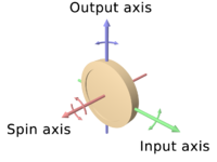
The axle of the spinning wheel defines the spin axis. The rotor is journaled to spin about an axis, which is always perpendicular to the axis of the inner gimbal. So the rotor possesses three degrees of rotational freedom and its axis possesses two. The wheel responds to a force applied about the input axis by a reaction force about the output axis.
The behaviour of a gyroscope can be most easily appreciated by consideration of the front wheel of a bicycle. If the wheel is leaned away from the vertical so that the top of the wheel moves to the left, the forward rim of the wheel also turns to the left. In other words, rotation on one axis of the turning wheel produces rotation of the third axis.
A gyroscope flywheel will roll or resist about the output axis depending upon whether the output gimbals are of a free- or fixed- configuration. Examples of some free-output-gimbal devices would be the attitude reference gyroscopes used to sense or measure the yaw,pitch and roll attitude angles in a spacecraft or aircraft.
 The centre of gravity of the rotor can be in a fixed position. The
rotor simultaneously spins about one axis and is capable of oscillating
about the two other axes, and, thus, except for its inherent resistance
due to rotor spin, it is free to turn in any direction about the fixed
point. Some gyroscopes have mechanical equivalents substituted for one
or more of the elements. For example, the spinning rotor may be
suspended in a fluid, instead of being pivotally mounted in gimbals. A control movement gyroscope
(CMG) is an example of a fixed-output-gimbal device that is used on
spacecraft to hold or maintain a desired attitude angle or pointing
direction using the gyroscopic resistance force.
The centre of gravity of the rotor can be in a fixed position. The
rotor simultaneously spins about one axis and is capable of oscillating
about the two other axes, and, thus, except for its inherent resistance
due to rotor spin, it is free to turn in any direction about the fixed
point. Some gyroscopes have mechanical equivalents substituted for one
or more of the elements. For example, the spinning rotor may be
suspended in a fluid, instead of being pivotally mounted in gimbals. A control movement gyroscope
(CMG) is an example of a fixed-output-gimbal device that is used on
spacecraft to hold or maintain a desired attitude angle or pointing
direction using the gyroscopic resistance force.
In some special cases, the outer gimbal (or its equivalent) may be omitted so that the rotor has only two degrees of freedom. In other cases, the centre of gravity of the rotor may be offset from the axis of oscillation, and, thus, the centre of gravity of the rotor and the centre of suspension of the rotor may not coincide
Variations
Gyrostat
A gyrostat is a variant of the gyroscope. It consists of a massive flywheel concealed in a solid casing. Its behaviour on a table, or with various modes of suspension or support, serves to illustrate the curious reversal of the ordinary laws of static equilibrium due to the gyrostatic behaviour of the interior invisible flywheel when rotated rapidly. The first gyrostat was designed by Lord Kelvin to illustrate the more complicated state of motion of a spinning body when free to wander about on a horizontal plane, like a top spun on the pavement, or a hoop or bicycle on the road. Kelvin also made use of gyrostats to develop mechanical theories of the elasticity of matter and of the ether; these theories are of purely historical interest today.
In modern times, the gyrostat concept is used in the design of attitude control systems for orbiting spacecraft and satellites. For instance, the Mir space station had three pairs of internally mounted flywheels known as gyrodynes or control moment gyros.
In physics, there are several systems whose dynamical equations resemble the equations of motion of a gyrostat. Examples include a solid body with a cavity filled with an inviscid, incompressible, homogeneous liquid, the static equilibrium configuration of a stressed elastic rod in elastica theory, the polarization dynamics of a light pulse propagating through a nonlinear medium,the Lorenz system in chaos theory, and the motion of an ion in a Penning trap mass spectrometer.
MEMS
A MEMS gyroscope takes the idea of the Foucault pendulum and uses a vibrating element, known as a MEMS (Micro Electro-Mechanical System). The MEMS-based gyro was initially made practical and producible by Systron Donner Inertial (SDI). Today, SDI is a large manufacturer of MEMS gyroscopes.
FOG
A fiber optic gyroscope (FOG) is a gyroscope that uses the interference of light to detect mechanical rotation. The sensor is a coil of as much as 5 km of optical fiber. The development of low-loss single-mode optical fiber in the early 1970s for the telecommunications industry enabled the development of Sagnac effect fiber optic gyros.
VSG or CVG
A vibrating structure gyroscope (VSG), also called a Coriolis Vibratory Gyroscope (CVG), uses a resonator made of different metallic alloys. It takes a position between the low-accuracy, low-cost MEMS gyroscope and the higher-accuracy and higher-cost FOG. Accuracy parameters are increased by using low-intrinsic damping materials, resonator vacuumization, and digital electronics to reduce temperature dependent drift and instability of control signals.
High-Q Wine-Glass Resonators for precise sensors like HRG or CRG
DTG
A dynamically tuned gyroscope (DTG) is a rotor suspended by a universal joint with flexure pivots. The flexure spring stiffness is independent of spin rate. However, the dynamic inertia (from the gyroscopic reaction effect) from the gimbal provides negative spring stiffness proportional to the square of the spin speed (Howe and Savet, 1964; Lawrence, 1998). Therefore, at a particular speed, called the tuning speed, the two moments cancel each other, freeing the rotor from torque, a necessary condition for an ideal gyroscope.
London moment
A London moment gyroscope relies on the quantum-mechanical phenomenon, whereby a spinning superconductor generates a magnetic field whose axis lines up exactly with the spin axis of the gyroscopic rotor. A magnetometer determines the orientation of the generated field, which is interpolated to determine the axis of rotation. Gyroscopes of this type can be extremely accurate and stable. For example, those used in the Gravity Probe B experiment measured changes in gyroscope spin axis orientation to better than 0.5 milliarcseconds (1.4×10⁻⁷ degrees) over a one-year period. This is equivalent to an angular separation the width of a human hair viewed from 32 kilometers (20 mi) away.
The GP-B gyro consists of a nearly-perfect spherical rotating mass made of fused quartz, which provides a dielectric support for a thin layer of niobium superconducting material. To eliminate friction found in conventional bearings, the rotor assembly is centered by the electric field from six electrodes. After the initial spin-up by a jet of helium which brings the rotor to 4,000 RPM, the polished gyroscope housing is evacuated to an ultra-high vacuum to further reduce drag on the rotor. Provided the suspension electronics remain powered, the extreme rotational symmetry, lack of friction, and low drag will allow the angular momentum of the rotor to keep it spinning for about 15,000 years.
A sensitive DC SQUID magnetometer able to discriminate changes as small as one quantum, or about 2 ×10⁻¹⁵ Wb, is used to monitor the gyroscope. A precession, or tilt, in the orientation of the rotor causes the London moment magnetic field to shift relative to the housing. The moving field passes through a superconducting pickup loop fixed to the housing, inducing a small electric current. The current produces a voltage across a shunt resistance, which is resolved to spherical coordinates by a microprocessor. The system is designed to minimize Lorentz torque on the rotor.
Modern uses
In addition to being used in compasses, aircraft, computer pointing devices, etc., gyroscopes have been introduced into consumer electronics. Since the gyroscope allows the calculation of orientation and rotation, designers have incorporated them into modern technology. The integration of the gyroscope has allowed for more accurate recognition of movement within a 3D space than the previous lone accelerometer within a number of smartphones.
Examples of Gyroscope in consumer electronics include HTC Titan, Nexus S, iPhone 4, Nokia 808 PureView,PlayStation 3 controller, Wii Remote, etc.
Gyroscopes based on other operating principles also exist, such as the electronic, microchip-packaged MEMS gyroscope devices found in consumer electronic devices, solid-state ring lasers, fibre optic gyroscopes, and the extremely sensitive quantum gyroscope.
Applications of gyroscopes include inertial navigation systems where magnetic compasses would not work (as in the Hubble telescope) or would not be precise enough (as in ICBMs), or for the stabilization of flying vehicles like radio-controlled helicopters or unmanned aerial vehicles. Due to their precision, gyroscopes are also used in gyrotheodolites to maintain direction in tunnel mining.
Description and diagram
Within mechanical systems or devices, a conventional gyroscope is a mechanism comprising a rotor journaled to spin about one axis, the journals of the rotor being mounted in an inner gimbal or ring; the inner gimbal is journaled for oscillation in an outer gimbal for a total of two gimbals.
The outer gimbal or ring, which is the gyroscope frame, is mounted so as to pivot about an axis in its own plane determined by the support. This outer gimbal possesses one degree of rotational freedom and its axis possesses none. The next inner gimbal is mounted in the gyroscope frame (outer gimbal) so as to pivot about an axis in its own plane that is always perpendicular to the pivotal axis of the gyroscope frame (outer gimbal). This inner gimbal has two degrees of rotational freedom.
The axle of the spinning wheel defines the spin axis. The rotor is journaled to spin about an axis, which is always perpendicular to the axis of the inner gimbal. So the rotor possesses three degrees of rotational freedom and its axis possesses two. The wheel responds to a force applied about the input axis by a reaction force about the output axis.
The behaviour of a gyroscope can be most easily appreciated by consideration of the front wheel of a bicycle. If the wheel is leaned away from the vertical so that the top of the wheel moves to the left, the forward rim of the wheel also turns to the left. In other words, rotation on one axis of the turning wheel produces rotation of the third axis.
A gyroscope flywheel will roll or resist about the output axis depending upon whether the output gimbals are of a free- or fixed- configuration. Examples of some free-output-gimbal devices would be the attitude reference gyroscopes used to sense or measure the pitch, roll and yaw attitude angles in a spacecraft or aircraft.

The outer gimbal or ring, which is the gyroscope frame, is mounted so as to pivot about an axis in its own plane determined by the support. This outer gimbal possesses one degree of rotational freedom and its axis possesses none. The next inner gimbal is mounted in the gyroscope frame (outer gimbal) so as to pivot about an axis in its own plane that is always perpendicular to the pivotal axis of the gyroscope frame (outer gimbal). This inner gimbal has two degrees of rotational freedom.
The axle of the spinning wheel defines the spin axis. The rotor is journaled to spin about an axis, which is always perpendicular to the axis of the inner gimbal. So the rotor possesses three degrees of rotational freedom and its axis possesses two. The wheel responds to a force applied about the input axis by a reaction force about the output axis.
The behaviour of a gyroscope can be most easily appreciated by consideration of the front wheel of a bicycle. If the wheel is leaned away from the vertical so that the top of the wheel moves to the left, the forward rim of the wheel also turns to the left. In other words, rotation on one axis of the turning wheel produces rotation of the third axis.
A gyroscope flywheel will roll or resist about the output axis depending upon whether the output gimbals are of a free- or fixed- configuration. Examples of some free-output-gimbal devices would be the attitude reference gyroscopes used to sense or measure the yaw,pitch and roll attitude angles in a spacecraft or aircraft.

In some special cases, the outer gimbal (or its equivalent) may be omitted so that the rotor has only two degrees of freedom. In other cases, the centre of gravity of the rotor may be offset from the axis of oscillation, and, thus, the centre of gravity of the rotor and the centre of suspension of the rotor may not coincide
Variations
Gyrostat
A gyrostat is a variant of the gyroscope. It consists of a massive flywheel concealed in a solid casing. Its behaviour on a table, or with various modes of suspension or support, serves to illustrate the curious reversal of the ordinary laws of static equilibrium due to the gyrostatic behaviour of the interior invisible flywheel when rotated rapidly. The first gyrostat was designed by Lord Kelvin to illustrate the more complicated state of motion of a spinning body when free to wander about on a horizontal plane, like a top spun on the pavement, or a hoop or bicycle on the road. Kelvin also made use of gyrostats to develop mechanical theories of the elasticity of matter and of the ether; these theories are of purely historical interest today.
In modern times, the gyrostat concept is used in the design of attitude control systems for orbiting spacecraft and satellites. For instance, the Mir space station had three pairs of internally mounted flywheels known as gyrodynes or control moment gyros.
In physics, there are several systems whose dynamical equations resemble the equations of motion of a gyrostat. Examples include a solid body with a cavity filled with an inviscid, incompressible, homogeneous liquid, the static equilibrium configuration of a stressed elastic rod in elastica theory, the polarization dynamics of a light pulse propagating through a nonlinear medium,the Lorenz system in chaos theory, and the motion of an ion in a Penning trap mass spectrometer.
MEMS
A MEMS gyroscope takes the idea of the Foucault pendulum and uses a vibrating element, known as a MEMS (Micro Electro-Mechanical System). The MEMS-based gyro was initially made practical and producible by Systron Donner Inertial (SDI). Today, SDI is a large manufacturer of MEMS gyroscopes.
FOG
A fiber optic gyroscope (FOG) is a gyroscope that uses the interference of light to detect mechanical rotation. The sensor is a coil of as much as 5 km of optical fiber. The development of low-loss single-mode optical fiber in the early 1970s for the telecommunications industry enabled the development of Sagnac effect fiber optic gyros.
VSG or CVG
A vibrating structure gyroscope (VSG), also called a Coriolis Vibratory Gyroscope (CVG), uses a resonator made of different metallic alloys. It takes a position between the low-accuracy, low-cost MEMS gyroscope and the higher-accuracy and higher-cost FOG. Accuracy parameters are increased by using low-intrinsic damping materials, resonator vacuumization, and digital electronics to reduce temperature dependent drift and instability of control signals.
High-Q Wine-Glass Resonators for precise sensors like HRG or CRG
DTG
A dynamically tuned gyroscope (DTG) is a rotor suspended by a universal joint with flexure pivots. The flexure spring stiffness is independent of spin rate. However, the dynamic inertia (from the gyroscopic reaction effect) from the gimbal provides negative spring stiffness proportional to the square of the spin speed (Howe and Savet, 1964; Lawrence, 1998). Therefore, at a particular speed, called the tuning speed, the two moments cancel each other, freeing the rotor from torque, a necessary condition for an ideal gyroscope.
London moment
A London moment gyroscope relies on the quantum-mechanical phenomenon, whereby a spinning superconductor generates a magnetic field whose axis lines up exactly with the spin axis of the gyroscopic rotor. A magnetometer determines the orientation of the generated field, which is interpolated to determine the axis of rotation. Gyroscopes of this type can be extremely accurate and stable. For example, those used in the Gravity Probe B experiment measured changes in gyroscope spin axis orientation to better than 0.5 milliarcseconds (1.4×10⁻⁷ degrees) over a one-year period. This is equivalent to an angular separation the width of a human hair viewed from 32 kilometers (20 mi) away.
The GP-B gyro consists of a nearly-perfect spherical rotating mass made of fused quartz, which provides a dielectric support for a thin layer of niobium superconducting material. To eliminate friction found in conventional bearings, the rotor assembly is centered by the electric field from six electrodes. After the initial spin-up by a jet of helium which brings the rotor to 4,000 RPM, the polished gyroscope housing is evacuated to an ultra-high vacuum to further reduce drag on the rotor. Provided the suspension electronics remain powered, the extreme rotational symmetry, lack of friction, and low drag will allow the angular momentum of the rotor to keep it spinning for about 15,000 years.
A sensitive DC SQUID magnetometer able to discriminate changes as small as one quantum, or about 2 ×10⁻¹⁵ Wb, is used to monitor the gyroscope. A precession, or tilt, in the orientation of the rotor causes the London moment magnetic field to shift relative to the housing. The moving field passes through a superconducting pickup loop fixed to the housing, inducing a small electric current. The current produces a voltage across a shunt resistance, which is resolved to spherical coordinates by a microprocessor. The system is designed to minimize Lorentz torque on the rotor.
Modern uses
In addition to being used in compasses, aircraft, computer pointing devices, etc., gyroscopes have been introduced into consumer electronics. Since the gyroscope allows the calculation of orientation and rotation, designers have incorporated them into modern technology. The integration of the gyroscope has allowed for more accurate recognition of movement within a 3D space than the previous lone accelerometer within a number of smartphones.
Examples of Gyroscope in consumer electronics include HTC Titan, Nexus S, iPhone 4, Nokia 808 PureView,PlayStation 3 controller, Wii Remote, etc.
TRANSMISSION (mechanics)
A machine consists of a power source and a power transmission system, which provides controlled application of the power. Merriam-Webster defines transmission as an assembly of parts including the speed-changing gears and the propeller shaft by which the power is transmitted from an engine to a live axle.Often transmission refers simply to the gearbox that uses gears and gear trains to provide speed and torque conversions from a rotating power source to another device.
In British English, the term transmission refers to the whole drive train, including clutch, gearbox, prop shaft (for rear-wheel drive), differential, and final drive shafts. In American English, however, a gearbox is any device that converts speed and torque, whereas a transmission is a type of gearbox that can be "shifted" to dynamically change the speed-torque ratio such as in a vehicle.
The most common use is in motor vehicles, where the transmission adapts the output of the internal combustion engine to the drive wheels. Such engines need to operate at a relatively high rotational speed, which is inappropriate for starting, stopping, and slower travel. The transmission reduces the higher engine speed to the slower wheel speed, increasing torque in the process. Transmissions are also used on pedal bicycles, fixed machines, and anywhere rotational speed and torque must be adapted.
Often, a transmission has multiple gear ratios (or simply "gears"), with the ability to switch between them as speed varies. This switching may be done manually (by the operator), or automatically. Directional (forward and reverse) control may also be provided. Single-ratio transmissions also exist, which simply change the speed and torque (and sometimes direction) of motor output.
In motor vehicles, the transmission generally is connected to the engine crankshaft via a flywheel and/or clutch and/or fluid coupling, partly because internal combustion engines cannot run below a particular speed. The output of the transmission is transmitted via driveshaft to one or more differentials, which in turn, drive the wheels. While a differential may also provide gear reduction, its primary purpose is to permit the wheels at either end of an axle to rotate at different speeds (essential to avoid wheel slippage on turns) as it changes the direction of rotation.
Conventional gear/belt transmissions are not the only mechanism for speed/torque adaptation. Alternative mechanisms include torque converters and power transformation (for example, diesel-electric transmission and hydraulic drive system). Hybrid configurations also exist.
The simplest transmissions, often called gearboxes to reflect their simplicity (although complex systems are also called gearboxes in the vernacular), provide gear reduction (or, more rarely, an increase in speed), sometimes in conjunction with a right-angle change in direction of the shaft (typically in helicopters, see picture). These are often used on PTO-powered agricultural equipment, since the axial PTO shaft is at odds with the usual need for the driven shaft, which is either vertical (as with rotary mowers), or horizontally extending from one side of the implement to another (as with manure spreaders, flail mowers, and forage wagons). More complex equipment, such as silage choppers and snowblowers, have drives with outputs in more than one direction.
The gearbox in a wind turbine converts the slow, high-torque rotation of the turbine into much faster rotation of the electrical generator. These are much larger and more complicated than the PTO gearboxes in farm equipment. They weigh several tons and typically contain three stages to achieve an overall gear ratio from 40:1 to over 100:1, depending on the size of the turbine. (For aerodynamic and structural reasons, larger turbines have to turn more slowly, but the generators all have to rotate at similar speeds of several thousand rpm.) The first stage of the gearbox is usually a planetary gear, for compactness, and to distribute the enormous torque of the turbine over more teeth of the low-speed shaft. Durability of these gearboxes has been a serious problem for a long time.
Regardless of where they are used, these simple transmissions all share an important feature: the gear ratio cannot be changed during use. It is fixed at the time the transmission is constructed.
Automotive basics
The need for a transmission in an automobile is a consequence of the characteristics of the internal combustion engine. Engines typically operate over a range of 600 to about 7000 revolutions per minute (though this varies, and is typically less for diesel engines), while the car's wheels rotate between 0 rpm and around 1800 rpm.
Furthermore, the engine provides its highest torque and power outputs unevenly across the rev range resulting in a torque band and a power band. Often the greatest torque is required when the vehicle is moving from rest or traveling slowly, while maximum power is needed at high speed. Therefore, a system that transforms the engine's output so that it can supply high torque at low speeds, but also operate at highway speeds with the motor still operating within its limits, is required. Transmissions perform this transformation.
The dynamics of a car vary with speed: at low speeds, acceleration is limited by the inertia of vehicular gross mass; while at cruising or maximum speeds wind resistance is the dominant barrier.
Many transmissions and gears used in automotive and truck applications are contained in a cast iron case, though more frequently aluminium is used for lower weight especially in cars. There are usually three shafts: a mainshaft, a countershaft, and an idler shaft.
The mainshaft extends outside the case in both directions: the input shaft towards the engine, and the output shaft towards the rear axle (on rear wheel drive carsfront wheel drives generally have the engine and transmission mounted transversely, the differential being part of the transmission assembly.) The shaft is suspended by the main bearings, and is split towards the input end. At the point of the split, a pilot bearing holds the shafts together. The gears and clutches ride on the mainshaft, the gears being free to turn relative to the mainshaft except when engaged by the clutches.
Types of automobile transmissions include manual, automatic or semi-automatic transmission.
Manual
Manual transmissions come in two basic types:
A simple but rugged sliding-mesh or unsynchronized/non-synchronous system, where straight-cut spur gear sets spin freely, and must be synchronized by the operator matching engine revs to road speed, to avoid noisy and damaging clashing of the gears
The now common constant-mesh gearboxes, which can include non-synchronised, or synchronized/synchromesh systems, where typically diagonal cut helical (or sometimes either straight-cut, or double-helical) gear sets are constantly "meshed" together, and a dog clutch is used for changing gears. On synchromesh boxes, friction cones or "synchro-rings" are used in addition to the dog clutch to closely match the rotational speeds of the two sides of the (declutched) transmission before making a full mechanical engagement.
The former type was standard in many vintage cars (alongside e.g. epicyclic and multi-clutch systems) before the development of constant-mesh manuals and hydraulic-epicyclic automatics, older heavy-duty trucks, and can still be found in use in some agricultural equipment. The latter is the modern standard for on- and off-road transport manual and semi-automatic transmission, although it may be found in many forms; e.g., non-synchronised straight-cut in racetrack or super-heavy-duty applications, non-synchro helical in the majority of heavy trucks and motorcycles and in certain classic cars (e.g. the Fiat 500), and partly or fully synchronised helical in almost all modern manual-shift passenger cars and light trucks.
Manual transmissions are the most common type outside North America and Australia. They are cheaper, lighter, usually give better performance, and fuel efficiency (although automatic transmissions with torque converter lockup and advanced electronic controls can provide similar results). It is customary for new drivers to learn, and be tested, on a car with a manual gear change. In Malaysia and Denmark all cars used for testing (and because of that, virtually all those used for instruction as well) have a manual transmission. In Japan, the Philippines, Germany, Poland, Italy, Israel, the Netherlands, Belgium, New Zealand, Austria, Bulgaria, the UK, Ireland. Sweden, Norway, Estonia, France, Spain, Switzerland, the Australian states of Victoria,Western Australia and Queensland, Finland, Latvia, Lithuania and the Czech Republic, a test pass using an automatic car does not entitle the driver to use a manual car on the public road; a test with a manual car is required.[citation needed] Manual transmissions are much more common than automatic transmissions in Asia, Africa, South America and Europe.
Manual transmissions can include both synchronized and unsynchronized gearing. For example, reverse gear is usually unsynchronised, as the drive is only expected to engage it when the vehicle is at a standstill. Many older (up to 1970s) cars also lacked syncro on first gear (for various reasons—cost, typically "shorter" overall gearing, engines typically having more low-end torque, the extreme wear on a frequently used first gear synchroniser ...), meaning it also could only be used for moving away from a stop unless the driver became adept at double-declutching and had a particular need to regularly downshift into the lowest gear.
Some manual transmissions have an extremely low ratio for first gear, called a creeper gear or granny gear. Such gears are usually not synchronized. This feature is common on pickup trucks tailored to trailer-towing, farming, or construction-site work. During normal on-road use, the truck is usually driven without using the creeper gear at all, and second gear is used from a standing start. Some off-road vehicles, most particularly the Willys Jeep and its descendents, also had transmissions with "granny first"s either as standard or an option, but this function is now more often provided for by a low-range transfer gearbox attached to a normal fully synchronised transmission.
Non-synchronous
Non-synchronous transmissions
Some commercial applications use non-synchronized manual transmissions that require a skilled operator. Depending on the country, many local, regional, and national laws govern operation of these types of vehicles (see Commercial Driver's License). This class may include commercial, military, agricultural, or engineering vehicles. Some of these may use combinations of types for multi-purpose functions. An example is a power take-off (PTO) gear. The non-synchronous transmission type requires an understanding of gear range, torque, engine power, and multi-functional clutch and shifter functions. Also see Double-clutching, and Clutch-brake sections of the main article.
Automatic
Most modern North American and Australian and some European and Japanese cars have an automatic transmission that selects an appropriate gear ratio without any operator intervention. They primarily use hydraulics to select gears, depending on pressure exerted by fluid within the transmission assembly. Rather than using a clutch to engage the transmission, a fluid flywheel, or torque converter is placed in between the engine and transmission. It is possible for the driver to control the number of gears in use or select reverse, though precise control of which gear is in use may or may not be possible.
Automatic transmissions are easy to use. However, in the past, automatic transmissions of this type have had a number of problems; they were complex and expensive, sometimes had reliability problems (which sometimes caused more expenses in repair), have often been less fuel-efficient than their manual counterparts (due to "slippage" in the torque converter), and their shift time was slower than a manual making them uncompetitive for racing. With the advancement of modern automatic transmissions this has changed.
Attempts to improve fuel efficiency of automatic transmissions include the use of torque converters that lock up beyond a certain speed or in higher gear ratios, eliminating power loss, and overdrive gears that automatically actuate above certain speeds. In older transmissions, both technologies could be intrusive, when conditions are such that they repeatedly cut in and out as speed and such load factors as grade or wind vary slightly. Current computerized transmissions possess complex programming that both maximizes fuel efficiency and eliminates intrusiveness. This is due mainly to electronic rather than mechanical advances, though improvements in CVT technology and the use of automatic clutches have also helped. A few cars, including the 2013 Subuaru Impreza and the 2012 model of the Honda Jazz sold in the UK, actually claim marginally better fuel consumption for the CVT version than the manual version.
For certain applications, the slippage inherent in automatic transmissions can be advantageous. For instance, in drag racing, the automatic transmission allows the car to stop with the engine at a high rpm (the "stall speed") to allow for a very quick launch when the brakes are released. In fact, a common modification is to increase the stall speed of the transmission. This is even more advantageous for turbocharged engines, where the turbocharger must be kept spinning at high rpm by a large flow of exhaust to maintain the boost pressure and eliminate the turbo lag that occurs when the throttle suddenly opens on an idling engine.
Semi-automatic
A hybrid form of transmission where an integrated control system handles manipulation of the clutch automatically, but the driver can still—and may be required to—take manual control of gear selection. This is sometimes called a "clutchless manual", or "automated manual" transmission. Many of these transmissions allow the driver to fully delegate gear shifting choice to the control system, which then effectively acts as if it was a regular automatic transmission. They are generally designed using manual transmission "internals", and when used in passenger cars, have synchromesh operated helical constant mesh gear sets.
Early semi-automatic systems used a variety of mechanical and hydraulic systems—including centrifugal clutches, torque converters, electro-mechanical (and even electrostatic) and servo/solenoid controlled clutches—and control schemes—automatic declutching when moving the gearstick, pre-selector controls, centrifugal clutches with drum-sequential shift requiring the driver to lift the throttle for a successful shift, etc.—and some were little more than regular lock-up torque converter automatics with manual gear selection.
Most modern implementations, however, are standard or slightly modified manual transmissions (and very occasionally modified automatics—even including a few cases of CVTs with "fake" fixed gear ratios), with servo-controlled clutching and shifting under command of the central engine computer. These are intended as a combined replacement option both for more expensive and less efficient "normal" automatic systems, and for drivers who prefer manual shift but are no longer able to operate a clutch, and users are encouraged to leave the shift lever in fully automatic "drive" most of the time, only engaging manual-sequential mode for sporty driving or when otherwise strictly necessary.
Specific types of this transmission include: Easytronic, Tiptronic and Geartronic, as well as the systems used as standard in all ICE-powered Smart-MCC vehicles, and on geared step-through scooters such as the Honda Super Cub or Suzuki Address.
A dual-clutch transmission alternately uses two sets of internals, each with its own clutch, so that a "gearchange" actually only consists of one clutch engaging as the other disengages—providing a supposedly "seamless" shift with no break in (or jarring reuptake of) power transmission. Each clutch's attached shaft carries half of the total input gear complement (with a shared output shaft), including synchronised dog clutch systems that pre-select which of its set of ratios is most likely needed at the next shift, under command of a computerised control system. Specific types of this transmission include: Direct-Shift Gearbox.
There are also sequential transmissions that use the rotation of a drum to switch gears, much like those of a typical fully manual motorcycle. These can be designed with a manual or automatic clutch system, and may be found both in automobiles (particularly track and rally racing cars), motorcycles (typically light "step-thru" type city utility bikes, e.g., the Honda Super Cub) and quadbikes (often with a separately engaged reversing gear), the latter two normally using a scooter-style centrifugal clutch.
Bicycle gearing
Bicycles usually have a system for selecting different gear ratios. There are two main types: derailleur gears and hub gears. The derailleur type is the most common, and the most visible, using sprocket gears. Typically there are several gears available on the rear sprocket assembly, attached to the rear wheel. A few more sprockets are usually added to the front assembly as well. Multiplying the number of sprocket gears in front by the number to the rear gives the number of gear ratios, often called "speeds".
Hub gears use epicyclic gearing and are enclosed within the axle of the rear wheel. Because of the small space, they typically offer fewer different speeds, although at least one has reached 14 gear ratios and Fallbrook Technologies manufactures a transmission with technically infinite ratios.
Several attempts have been made to fit bicycles with an enclosed gearbox, giving obvious advantages for better lubrication, dirt-sealing and shifting. These have usually been in conjunction with a shaft drive, as a gearbox with a traditional chain would (like the hub gear) still have many of the derailleur's disadvantages for an exposed chain. Bicycle gearboxes are enclosed in a box replacing the traditional bottom bracket. The requirement for a modified frame has been a serious drawback to their adoption. One of the most recent attempts to provide a gearbox for bicycles is the 18 speed Pinion P1.18. This gives an enclosed gearbox, but still a traditional chain. When fitted to a rear suspension bike, it also retains a derailleur-like jockey cage chain tensioner, although without the derailleur's low ground clearance.
Causes for failure of bicycle gearing include: worn teeth, damage caused by a faulty chain, damage due to thermal expansion, broken teeth due to excessive pedaling force, interference by foreign objects, and loss of lubrication due to negligence.
Uncommon types
Dual clutch transmission
This arrangement is also sometimes known as a direct shift gearbox or powershift gearbox. It seeks to combine the advantages of a conventional manual shift with the qualities of a modern automatic transmission by providing different clutches for odd and even speed selector gears. When changing gear, the engine torque is transferred from one gear to the other continuously, so providing gentle, smooth gear changes without either losing power or jerking the vehicle. Gear selection may be manual, automatic (depending on throttle/speed sensors), or a 'sports' version combining both options.
Continuously variable
The continuously variable transmission (CVT) is a transmission in which the ratio of the rotational speeds of two shafts, as the input shaft and output shaft of a vehicle or other machine, can be varied continuously within a given range, providing an infinite number of possible ratios. The CVT allows the driver or a computer to select the relationship between the speed of the engine and the speed of the wheels within a continuous range. This can provide even better fuel economy if the engine constantly runs at a single speed. The transmission is, in theory, capable of a better user experience, without the rise and fall in speed of an engine, and the jerk felt when changing gears poorly.
CVTs are increasingly found on small cars, and especially high-gas-mileage or hybrid vehicles. On these platforms, the torque is limited because the electric motor can provide torque without changing the speed of the engine. By leaving the engine running at the rate that generates the best gas mileage for the given operating conditions, overall mileage can be improved over a system with a smaller number of fixed gears, where the system may be operating at peak efficiency only for a small range of speeds. CVTs are also found in agricultural equipment; due to the high-torque nature of these vehicles, mechanical gears are integrated to provide tractive force at high speeds.
Infinitely variable
The IVT is a specific type of CVT that includes not only an infinite number of gear ratios, but an infinite range as well. This is a turn of phrase, it actually refers to CVTs that are able to include a "zero ratio", where the input shaft can turn without any motion of the output shaft while remaining in gear. Zero output implies infinite ratios, as any "high gear" ratio is an infinite number of times higher than the zero "low gear".
Most (if not all) IVTs result from the combination of a CVT with an epicyclic gear system with a fixed ratio. The combination of the fixed ratio of the epicyclic gear with a specific matching ratio in the CVT side results in zero output. For instance, consider a transmission with an epicyclic gear set to 1:−1 gear ratio; a 1:1 reverse gear. When the CVT side is set to 1:1 the two ratios add up to zero output. The IVT is always engaged, even during its zero output. When the CVT is set to higher values it operates conventionally, with increasing forward ratios.
In practice, the epicyclic gear may be set to the lowest possible ratio of the CVT, if reversing is not needed or is handled through other means. Reversing can be incorporated by setting the epicyclic gear ratio somewhat higher than the lowest ratio of the CVT, providing a range of reverse ratios.
Electric variable
The Electric Variable Transmission (EVT) combines a transmission with an electric motor to provide the illusion of a single CVT. In the common implementation, a gasoline engine is connected to a traditional transmission, which is in turn connected to an epicyclic gear system's planet carrier. An electric motor/generator is connected to the central "sun" gear, which is normally un-driven in typical epicyclic systems. Both sources of power can be fed into the transmission's output at the same time, splitting power between them. In common examples, between one-quarter and half of the engine's power can be fed into the sun gear. Depending on the implementation, the transmission in front of the epicyclic system may be greatly simplified, or eliminated completely. EVTs are capable of continuously modulating output/input speed ratios like mechanical CVTs, but offer the distinct benefit of being able to also apply power from two different sources to one output, as well as potentially reducing overall complexity dramatically.
In typical implementations, the gear ratio of the transmission and epicyclic system are set to the ratio of the common driving conditions, say highway speed for a car, or city speeds for a bus. When the drivers presses on the gas, the associated electronics interprets the pedal position and immediately sets the gasoline engine to the RPM that provides the best gas mileage for that setting. As the gear ratio is normally set far from the maximum torque point, this set-up would normally result in very poor acceleration. Unlike gasoline engines, electric motors offer efficient torque across a wide selection of RPM, and are especially effective at low settings where the gasoline engine is inefficient. By varying the electrical load or supply on the motor attached to the sun gear, additional torque can be provided to make up for the low torque output from the engine. As the vehicle accelerates, the power to the motor is reduced and eventually ended, providing the illusion of a CVT.
The canonical example of the EVT is Toyota's Hybrid Synergy Drive. This implementation has no conventional transmission, and the sun gear always receives 28% of the torque from the engine. This power can be used to operate any electrical loads in the vehicle, recharging the batteries, powering the entertainment system, or running the air conditioning. Any residual power is then fed back into a second motor that powers the output of the drivetrain directly. At highway speeds this additional generator/motor pathway is less efficient than simply powering the wheels directly. However, during acceleration, the electrical path is much more efficient than engine operating so far from its torque point. GM uses a similar system in the Allison Bus hybrid powertrains and the Tahoe and Yukon pick-up trucks, but these use a two-speed transmission in front of the epicyclic system, and the sun gear receives close to half the total power.
Non-direct
Electric
Electric transmissions convert the mechanical power of the engine(s) to electricity with electric generators and convert it back to mechanical power with electric motors. Electrical or electronic adjustable-speed drive control systems are used to control the speed and torque of the motors. If the generators are driven by turbines, such arrangements are called turbo-electric transmission. Likewise installations powered by diesel-engines are called diesel-electric.
Diesel-electric arrangements are used on many railway locomotives, ships, large mining trucks, and some bulldozers. In these cases, each driven wheel is equipped with its own electric motor, which can be fed varying electrical power to provide any required torque or power output for each wheel independently. This produces a much simpler solution for multiple driven wheels in very large vehicles, where drive shafts would be much larger or heavier than the electrical cable that can provide the same amount of power. It also improves the ability to allow different wheels to run at different speeds, which is useful for steered wheels in large construction vehicles.
Hydrostatic
Hydrostatic transmissions transmit all power hydraulically, using the components of hydraulic machinery. They are similar to electrical transmissions, but hydraulic fluid as the power distribution system rather than electricity.
The transmission input drive is a central hydraulic pump and final drive unit(s) is/are a hydraulic motor, or hydraulic cylinder (see: swashplate). Both components can be placed physically far apart on the machine, being connected only by flexible hoses. Hydrostatic drive systems are used on excavators, lawn tractors, forklifts, winch drive systems, heavy lift equipment, agricultural machinery, earth-moving equipment, etc. An arrangement for motor-vehicle transmission was probably used on the Ferguson F-1 P99 racing car in about 1961.
The Human Friendly Transmission of the Honda DN-01 is hydrostatic.
Hydrodynamic
If the hydraulic pump and/or hydraulic motor make use of the hydrodynamic effects of the fluid flow, i.e. pressure due to a change in the fluid's momentum as it flows through vanes in a turbine. The pump and motor usually consist of rotating vanes without seals and are typically placed in close proximity. The transmission ratio can be made to vary by means of additional rotating vanes, an effect similar to varying the pitch of an airplane propeller.
The torque converter in most automotive automatic transmissions is, in itself, a hydrodynamic transmission. Hydrodynamic transmissions are used in many passenger rail vehicles, those that are not using electrical transmissions. In this application the advantage of smooth power delivery may outweigh the reduced efficiency caused by turbulence energy losses in the fluid.
Wednesday, 11 September 2013
SPOILER
A spoiler is an automotive aerodynamic device whose intended design function is to 'spoil' unfavorable air movement across a body of a vehicle in motion, usually described as turbulence or drag. Spoilers on the front of a vehicle are often called air dams, because in addition to directing air flow they also reduce the amount of air flowing underneath the vehicle which generally reduces aerodynamic lift and drag. Spoilers are often fitted to race and high-performance sports cars, although they have become common on passenger vehicles as well. Some spoilers are added to cars primarily for styling purposes and have either little aerodynamic benefit or even make the aerodynamics worse.
Spoilers for cars are often incorrectly confused with, or the term used interchangeably with, wings. Automotive wings are devices whose intended design is to generate downforce as air passes around them, not simply disrupt existing airflow patterns.
Operation
Since spoiler is a term describing an application, the operation of a spoiler varies depending on the particular effect it's trying to spoil. Most common spoiler functions include disrupting some type of airflow passing over and around a moving vehicle. A common spoiler diffuses air by increasing amounts of turbulence flowing over the shape, "spoiling" the laminar flow and providing a cushion for the laminar boundary layer. However, other types of airflow may require the spoiler to operate differently and take on vastly different physical characteristics.
Passenger vehicles
The goal of many spoilers used in passenger vehicles is to reduce drag and increase fuel efficiency. Passenger vehicles can be equipped with front and rear spoilers. Front spoilers, found beneath the bumper, are mainly used to decrease the amount of air going underneath the vehicle to reduce the drag coefficient and lift.
Sports cars are most commonly seen with front and rear spoilers. Even though these vehicles typically have a more rigid chassis and a stiffer suspension to aid in high speed maneuverability, a spoiler can still be beneficial. This is because many vehicles have a fairly steep downward angle going from the rear edge of the roof down to the trunk or tail of the car which may cause air flow separation. The flow of air becomes turbulent and a low-pressure zone is created, increasing drag and instability (see Bernoulli effect). Adding a rear spoiler could be considered to make the air "see" a longer, gentler slope from the roof to the spoiler, which helps to delay flow separation and the higher pressure in front of the spoiler can help reduce the lift on the car by creating downforce. This may reduce drag in certain instances and will generally increase high speed stability due to the reduced rear lift.
Due to their association with racing, spoilers are often viewed as "sporty" by consumers.
Material types
Spoilers are usually made of:
ABS plastic: Most original equipment manufacturers create spoilers produced by casting ABS plastic with various admixtures, which bring in plasticity to this inexpensive but fragile material. Frailness is a main disadvantage of plastic, which increases with product age and is caused by the evaporation of volatile phenols.
Fiberglass: Used in car parts production due to the low cost of the materials. Fiberglass spoilers consist of fiberglass cloth infilled with a thermosetting resin . Fiberglass is sufficiently durable and workable, but has become unprofitable for large scale production due to the amount of labor.
Silicon: More recently, many auto accessory manufacturers are using silicon-organic polymers. The main benefit of this material is its phenomenal plasticity. Silicon possesses extra high thermal characteristics and provides a longer product lifetime.
Carbon fiber: Carbon fiber is light weight, durable, but also a very expensive material. Due to the very large amount of manual labor, large scale production cannot widely use carbon fiber in automobile parts production currently.
Other common spoiler types
Front spoilers: A front spoiler (air dam) is positioned under or integrated with the front bumper. In racing, this spoiler is used to control the dynamics of handling related to the air in front of the vehicle. This can be to improve the drag coefficient of the body of the vehicle at speed, or to generate downforce. In passenger vehicles, the focus shifts more to directing the airflow into the engine bay for cooling purposes.
Truck bed spoiler: This attaches only to the top of the truck bed rails near the rear. Used with a bed cover, this spoiler is intended to reduce the air profile of the steep drop-off from the tailgate.
Truck cab spoiler: This is purposed the same as above, except focusing on the drop-off from the cab of the truck.
Other vehicles
Heavy trucks, like long haul tractors, may also have a spoiler on the top of the cab in order to lessen drag caused from air resistance from the trailer it's towing, which may be taller than the cab and reduce the aerodynamics of the vehicle dramatically without the use of this spoiler. The trailers they pull can also be fitted with under-side spoilers that angle outward to deflect passing air away from the rear axle's wheels.
Trains may use spoilers to induce drag (like an air brake). A new prototype Japanese high-speed train, the Fastech 360 is designed to reach speeds of 400 kilometres per hour (250 mph). Its nose is specifically designed to spoil a wind effect associated with passing through tunnels, and it can deploy 'ears' which act to slow the train in case of emergency by increasing its drag.
Some modern race cars employ a situational spoiler called a roof flap. The body of the car is designed to generate downforce while driving forward. These roof flaps deploy when the body of the car is rotated so it is traveling in reverse, a condition where the body instead generates lift. The roof flaps deploy because they are recessed into a pocket in the roof. The low pressure above this pocket will cause the flaps to deploy, and counteract some of the lift generated by the car, making it more resistant to coming out of contact with the ground. These devices were introduced in 1994 in NASCAR following Rusty Wallace's crash at Talladega.
Whale tail
When the Porsche 911 Turbo debuted in August 1974, with large, flared, rear spoilers, they were immediately dubbed whale tails.Designed to reduce rear-end lift and so keep the car from oversteering at high speeds, the rubber-edges of the whale tail spoilers were thought to be "pedestrian friendly". The Turbo, with its whale tail, became an instant hit. It also became one of the world's most recognizable sports cars, remaining in production for the next two decades in one form or another, with more than 23,000 sold by 1989, although from 1978, the rear spoiler was redesigned and dubbed 'teatray' on account of its raised sides. The Porsche 911 whale tails were used in conjunction with a chin spoiler attached to the front valence panel, which, according to some sources, did not enhance aerodynamic stability. It has been found to be less effective in multiplying downforce than newer technologies like an airfoil,"rear wing running across the base of the tailgate window", or "an electronically controlled wing that deploys at about 50 mph". (80 km/h).
FLYWHEEL
A flywheel is a rotating mechanical device that is used to store rotational energy. Flywheels have a significant moment of inertia and thus resist changes in rotational speed. The amount of energy stored in a flywheel is proportional to the square of its rotational speed. Energy is transferred to a flywheel by applying torque to it, thereby increasing its rotational speed, and hence its stored energy. Conversely, a flywheel releases stored energy by applying torque to a mechanical load, thereby decreasing its rotational speed.
Common uses of a flywheel include:
Providing continuous energy when the energy source is discontinuous. For example, flywheels are used in reciprocating engines because the energy source, torque from the engine, is intermittent.
Delivering energy at rates beyond the ability of a continuous energy source. This is achieved by collecting energy in the flywheel over time and then releasing the energy quickly, at rates that exceed the abilities of the energy source.
Controlling the orientation of a mechanical system. In such applications, the angular momentum of a flywheel is purposely transferred to a load when energy is transferred to or from the flywheel.
Flywheels are typically made of steel and rotate on conventional bearings; these are generally limited to a revolution rate of a few thousand RPM. Some modern flywheels are made of carbon fiber materials and employ magnetic bearings, enabling them to revolve at speeds up to 60,000 RPM.
Applications
Flywheels are often used to provide continuous energy in systems where the energy source is not continuous. In such cases, the flywheel stores energy when torque is applied by the energy source, and it releases stored energy when the energy source is not applying torque to it. For example, a flywheel is used to maintain constant angular velocity of the crankshaft in a reciprocating engine. In this case, the flywheel—which is mounted on the crankshaft—stores energy when torque is exerted on it by a firing piston, and it releases energy to its mechanical loads when no piston is exerting torque on it. Other examples of this are friction motors, which use flywheel energy to power devices such as toy cars.
A flywheel may also be used to supply intermittent pulses of energy at transfer rates that exceed the abilities of its energy source, or when such pulses would disrupt the energy supply (e.g., public electric network). This is achieved by accumulating stored energy in the flywheel over a period of time, at a rate that is compatible with the energy source, and then releasing that energy at a much higher rate over a relatively short time. For example, flywheels are used in riveting machines to store energy from the motor and release it during the riveting operation.
The phenomenon of precession has to be considered when using flywheels in vehicles. A rotating flywheel responds to any momentum that tends to change the direction of its axis of rotation by a resulting precession rotation. A vehicle with a vertical-axis flywheel would experience a lateral momentum when passing the top of a hill or the bottom of a valley (roll momentum in response to a pitch change). Two counter-rotating flywheels may be needed to eliminate this effect. This effect is leveraged in reaction wheels, a type of flywheel employed in satellites in which the flywheel is used to orient the satellite's instruments without thruster rockets.
Physics
A flywheel is a spinning wheel or disc with a fixed axle so that rotation is only about one axis. Energy is stored in the rotor as kinetic energy, or more specifically, rotational energy:
E_k=\frac{1}{2} I \omega^2
Where:
ω is the angular velocity, and
I is the moment of inertia of the mass about the center of rotation. The moment of inertia is the measure of resistance to torque applied on a spinning object (i.e. the higher the moment of inertia, the slower it will spin when a given force is applied).
The moment of inertia for a solid cylinder is I = \frac{1}{2} mr^2,
for a thin-walled empty cylinder is I = m r^2,
and for a thick-walled empty cylinder is I = \frac{1}{2} m({r_{external}}^2 + {r_{internal}}^2),
Where m denotes mass, and r denotes a radius.
When calculating with SI units, the standards would be for mass, kilograms; for radius, meters; and for angular velocity, radians per second. The resulting answer would be in joules.
The amount of energy that can safely be stored in the rotor depends on the point at which the rotor will warp or shatter. The hoop stress on the rotor is a major consideration in the design of a flywheel energy storage system.
\sigma_t = \rho r^2 \omega^2 \
Where:
\sigma_t is the tensile stress on the rim of the cylinder
\rho is the density of the cylinder
r is the radius of the cylinder, and
\omega is the angular velocity of the cylinder.
This formula can also be simplified using specific tensile strength and tangent velocity:
\frac{\sigma_t}{\rho} = v^2
Where:
\frac{\sigma_t}{\rho} is the specific tensile strength of the material
v is the tangent velocity of the rim.
Subscribe to:
Comments (Atom)